
Views: 0 Author: Site Editor Publish Time: 2026-11-11 Origin: Site


In the chaotic and terrifying environment of a subterranean vehicular fire, empirical data and historical incident analyses reveal a sobering reality. Toxic fumes and zero-visibility conditions incapacitate trapped motorists long before flames ever reach them. To combat this severe hazard, simply bolting powerful extraction equipment to the ceiling falls completely short of a true solution. If the longitudinal distance between these units is miscalculated, the entire safety infrastructure will catastrophically fail. This failure manifests as a deadly fluid dynamics phenomenon known as smoke back-layering. During this event, superheated gases travel along the ceiling against the direction of the intended airflow and engulf evacuees.
The ultimate countermeasure for modern underground infrastructure relies on the precise implementation of longitudinal extraction systems. However, the operational success of these units depends entirely on their strategic placement. Spacing is the absolute deciding factor in maintaining sufficient air velocity to push toxic clouds out efficiently. This ensures a clear, breathable path for escape. This comprehensive guide will dissect the fluid dynamics behind equipment spacing, the critical role of aerodynamic pushing force, cross-tube protection, and how to optimize your overall Fire Ventilation design.
Spacing is Critical: Improper longitudinal intervals disrupt airflow momentum. This leads to dangerous accumulation and back-layering during emergencies.
Force Matters: The effective mechanical pushing power of a unit dictates exactly how far apart installations can be placed while maintaining reliable airflow.
Escape Route Safety: Strategic placement is strictly required near pedestrian egress points to ensure evacuees have a pressurized, breathable escape route.
System Synergy: Successful hazard mitigation relies on the perfect engineering balance of equipment capacity, longitudinal gaps, and subterranean geometry.
Quality Equipment: Investing in high-performance aerodynamic designs reduces the total number of units needed. This lowers both initial installation and long-term maintenance costs.
Establishing a foundational understanding of the hardware is necessary before analyzing complex mathematical spacing calculations. Specialized axial units have become the undisputed industry standard for managing subterranean air quality and emergency extraction.
These highly specialized, high-velocity axial machines are typically mounted directly to the structural concrete ceiling or along the upper curvature of the side walls. Unlike standard commercial HVAC components, these ruggedized units are engineered to withstand extreme thermal shock. For instance, premium models are rigorously tested to operate in temperatures exceeding 400°C for up to two hours. Their primary function operates on a dual-purpose model. During normal daily commutes, they induce a steady longitudinal draft that scrubs vehicle exhaust, carbon monoxide, and tire particulate matter out of the enclosed space. In contrast, during emergency scenarios, they instantly ramp up to maximum RPMs to clear toxic clouds. This rapid response creates a survivable environment for trapped individuals and approaching first responders.
Historically, civil engineers relied on complex transverse systems. These legacy designs required massive, labyrinthine networks of supply and exhaust ducts built directly into the concrete. While highly effective, they were exceptionally expensive to excavate and notoriously difficult to maintain. Consequently, modern infrastructure projects have largely abandoned them in favor of longitudinal strategies. This modern method cleverly leverages the main traffic tube itself as the primary airway. By utilizing high-velocity axial units, contractors achieve a highly cost-effective solution offering near-instantaneous response times. The hazard is driven linearly toward the nearest portal or vertical extraction shaft.
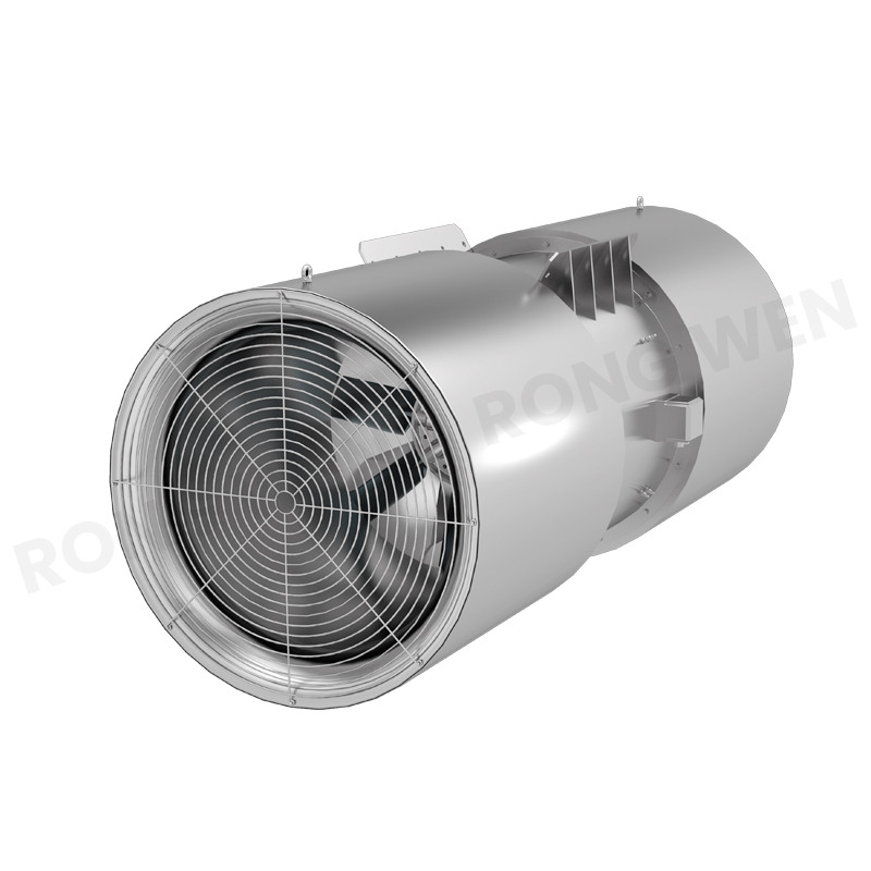
The beating heart of any longitudinal strategy is the preservation of continuous air momentum. The direct, unforgiving correlation between installation intervals and visibility clearance cannot be overstated. If the layout is flawed, the most expensive hardware becomes little more than ceiling ornaments.
Back-layering is a terrifying fluid dynamics issue. When a fire ignites, the extreme buoyancy of the rapidly expanding hot gases causes them to rise and flow backwards along the ceiling. They move directly against the intended ventilation current. To overpower this, the system must achieve critical velocity. This is the exact, non-negotiable airspeed required to halt the reverse flow. Correct installation intervals ensure a continuous, unbroken push of air. If the gaps are too wide, the air velocity sags below this critical threshold in the dead zones between units. This pressure drop allows the toxic plume to reverse course and endanger anyone trapped behind the incident.
Understanding these longitudinal dynamics is much easier when visualizing a high-stakes relay race. The mechanical units act like runners passing a baton. In this context, the baton is the kinetic energy of the airflow. When one machine accelerates the air mass, that jet stream travels a specific distance before surface friction bleeds its energy away. The rough concrete walls and stationary vehicles act as massive aerodynamic brakes. The subsequent unit must be positioned exactly where that momentum begins to wane. It catches the fading airflow and accelerates it once again. If the runners are too far apart, the momentum stalls, and the system fails. Meticulous Smoke Control engineering guarantees overlapping velocity profiles, ensuring a seamless sweep toward the exit.
To accurately map out installation blueprints, project managers must look beyond basic cubic-feet-per-minute metrics. Real-world emergency extraction focuses entirely on the raw mechanics of kinetic force.
In the context of subterranean environments, performance is primarily measured in Newtons. While volumetric flow looks great on a spec sheet, it is the actual mechanical pushing force that overcomes immense aerodynamic drag. The air pushed by the impellers must forcefully scrub against wall friction and navigate the jagged drag coefficients created by hundreds of stationary vehicles. Ultimately, the effective Thrust generated by the unit determines the permissible longitudinal gaps between installations. For example, utilizing an SDS Series unit with a 1250mm impeller diameter can yield pushing forces well over 1500 Newtons, allowing for highly optimized spacing.
General engineering rules of thumb often suggest plotting installations at longitudinal intervals of 100 to 150 meters. Relying blindly on these generic rules is a recipe for disaster. The true distance depends heavily on the cross-sectional area of the tube and the verified laboratory ratings of the hardware. A vital concept here is installation efficiency. When a unit is bolted too close to the ceiling, the high-velocity jet stream creates severe friction against the concrete. This scrubbing effect can reduce the effective kinetic energy by up to 30%. If installation efficiency drops due to tight physical clearances, field engineers must compensate by pulling the units closer together to maintain the required critical velocity.
Engineers must rigorously account for several external, environmental, and behavioral variables when finalizing a blueprint. A rigid, one-size-fits-all approach inevitably leads to catastrophic system failure under pressure.
Air naturally prefers the path of least resistance in a straight line. When an underground route features significant curves, sweeping bends, or varying gradients, the straight jet stream generated by the impellers violently collides with the outer curvature of the wall. This collision causes immediate flow separation and a rapid dissipation of kinetic energy. To counteract this severe aerodynamic penalty, curved sections strictly require much tighter installation spacing to sustain continuous velocity.
The anticipated flow of traffic drastically alters mathematical models. In unidirectional tubes, the natural movement of commuting vehicles creates a helpful piston effect that aids daily air circulation. However, during an emergency, traffic grinds to a halt. A massive traffic jam creates an impenetrable wall of aerodynamic resistance. Bidirectional routes face even steeper challenges because the hardware must be fully reversible. Overcoming high vehicle drag requires robust kinetic output and strategic, tightly packed groupings to force air through the narrow spaces between densely packed commercial freight.
Recent industry analyses highlight a dramatic shift in subterranean risk profiles due to the global surge in electric vehicle adoption. The anticipated size of a blaze is quantified as the Heat Release Rate in Megawatts. A standard combustion engine passenger car might generate 5 Megawatts, while a heavy goods vehicle can exceed 100 Megawatts. Modern Computational Fluid Dynamics modeling reveals that lithium-ion battery thermal runaways reach their peak Heat Release Rate significantly faster than traditional fires. They generate exceptionally buoyant, toxic plumes that are incredibly difficult to control. As a result, global safety standards are rapidly evolving. Forward-thinking engineers are now designing systems with much higher baseline thrust capacities and shorter longitudinal intervals. This aggressive approach is necessary to quickly overpower the severe thermal dynamics of modern EV incidents.
The ultimate goal of any emergency infrastructure is the preservation of human life. Connecting equipment layout to human evacuation routes is a non-negotiable, heavily regulated aspect of civil engineering.
Reinforced emergency pedestrian links are constructed between parallel traffic tubes. In the event of a catastrophic incident, trapped motorists abandon their vehicles and evacuate through heavy fire-rated doors into the adjacent, unaffected tube. Toxic fumes must never be allowed to breach these critical doors. Layout calculations must be perfectly tuned around these specific zones to create localized aerodynamic pressure shields. By strategically positioning hardware near these entrances, engineers ensure that fresh air is actively pushed into the evacuation route. This typically maintains a positive pressure of around 50 Pascals. This invisible shield forces hazards away from the doors, even when they are frantically opened by fleeing motorists. If the spacing is misaligned, a localized pressure drop occurs, allowing lethal gases to infiltrate the Cross Passage and compromise the entire evacuation strategy.
Even with advanced software modeling, practical on-site installation errors can cripple a meticulously designed system. Recognizing these common pitfalls helps project managers avoid costly rework and dangerous compliance failures.
One of the most frequent aerodynamic mistakes is mounting units too close to the ceiling or grouping them too tightly together in a bank. This triggers the Coanda effect. This fluid dynamics phenomenon occurs when a high-speed jet of air naturally bends and sticks to a nearby flat or convex surface due to a localized pressure drop. When this happens, the energy is scrubbed away against the concrete rather than moving the air mass down the corridor. This completely ruins the longitudinal strategy and leaves subsequent units starving for momentum.
A theoretical blueprint might dictate a mathematically perfect interval, but practical operations must take precedence. A severe operational mistake is bolting equipment into place without leaving adequate physical room for maintenance crews. Technicians dangling from scissor lifts must be able to safely access the terminal boxes, inspect the impellers, and calibrate vibration sensors. If units are jammed against cable trays or structural supports, routine servicing becomes impossible. This leads to silent mechanical degradation and eventual failure when the system is needed most.
Selecting the correct hardware is the final, crucial step in ensuring your mathematical models translate into real-world, life-saving performance. Abstract calculations must be paired with rugged, field-tested machinery.
When evaluating procurement options, project engineers must scrutinize specific technical certifications. High-temperature resistance is absolutely mandatory. You must verify that the nameplates carry authentic F300 or F400 ratings, proving the motors can survive 300°C or 400°C for up to two hours. Furthermore, fully reversible impeller capabilities are essential for bidirectional routes.
| Feature | Standard Commercial Fans | SDS Series High-Performance Jet Fans | Engineering Impact |
|---|---|---|---|
| Thermal Rating | Standard ambient or F200 | F300 / F400 Certified | Ensures continuous operation during peak fire temperatures without motor seizure. |
| Thrust Output | Low to Moderate | High Thrust up to 3500N | Allows for wider, safer installation intervals, reducing total unit count. |
| Impeller Design | Unidirectional only | 100% Fully Reversible | Critical for bidirectional traffic tubes; pushes smoke in either direction based on fire location. |
| Casing & Durability | Lightweight galvanized | Heavy-duty carbon steel with anti-corrosion coating | Withstands extreme subterranean moisture, vehicle exhaust corrosives, and thermal shock. |
High-quality manufacturing featuring superior aerodynamic blade design can achieve significantly higher effective kinetic output with lower electrical power consumption. Premium efficiency allows for wider, safer installation intervals. By sourcing a reliable Tunnel Jet Fan, contractors can lower overall project costs, simplify the electrical infrastructure, and guarantee flawless performance when lives are on the line.
The most advanced extraction hardware in the world is rendered useless if it is installed in the wrong location. Proper longitudinal spacing is the non-negotiable foundation that prevents back-layering, maximizes aerodynamic pushing force, and ensures that pedestrian escape routes remain pressurized and breathable. Protecting human life underground requires a holistic, uncompromising approach. It combines precise mathematical fluid dynamics with top-tier, rigorously tested equipment. Project managers, civil engineers, and safety contractors must continuously review their blueprints against evolving industry standards.
To ensure your next infrastructure project meets the highest global safety standards, explore the robust, high-thrust options available at centrifugal-fan.com. Equip your tunnels with hardware engineered to save lives.
Critical velocity is calculated using complex fluid dynamics equations that factor in the tunnel's cross-sectional area, the specific grade or slope of the roadway, and the anticipated Heat Release Rate of the fire. Engineers use Computational Fluid Dynamics software to determine the exact airspeed required to prevent hot gases from flowing against the ventilation current, ensuring smoke is pushed cleanly toward the exhaust portal.
Unidirectional fans are designed to push air in only one direction with maximum efficiency, making them ideal for tunnels where traffic only flows one way. Bidirectional fans feature specially designed symmetrical impellers that can instantly reverse their spin to push air with equal thrust in either direction. This is absolutely critical for two-way traffic tunnels, allowing emergency operators to push smoke away from trapped motorists regardless of where the fire starts.
While the exact distance varies heavily based on structural geometry, cross-sectional area, and equipment capacity, installations are typically spaced longitudinally every 100 to 150 meters. However, routes with severe curves, high traffic resistance, or heavy commercial freight often require much closer intervals to maintain the critical velocity needed for safety.
The equipment utilizes high-velocity kinetic force to create a powerful, unidirectional longitudinal draft. This continuous airflow pushes the toxic plume in one specific direction, preventing it from spreading backward over trapped vehicles and keeping the evacuation path completely clear for both motorists and incoming first responders.
In a subterranean environment, the system must overcome immense aerodynamic drag caused by rough concrete walls and tightly packed stationary vehicles. Kinetic force is the actual mechanical pushing power that overcomes this physical resistance to keep the heavy mass of air moving, making it the most critical metric for emergency design.
Absolutely. If units are spaced incorrectly, the airflow momentum will drop, creating localized low-pressure zones. This allows lethal gases to accumulate near emergency doors. Proper layout ensures a continuous, high-pressure flow that actively drives hazards away from these critical exit routes, keeping them safe and breathable.
The Coanda effect occurs when equipment is bolted too close to the ceiling or side walls. The high-speed air jet sticks to the adjacent concrete surface due to a pressure differential, creating severe friction. This drastically reduces the effective pushing power of the unit, disrupts the overall clearance strategy, and leaves the system unable to control the hazard.


