
Views: 0 Author: Site Editor Publish Time: 2026-08-24 Origin: Site


Exhaust or ventilation failure in 24/7 manufacturing, high-tech processing, and cleanroom environments carries severe operational and financial consequences. When continuous airflow stops, facilities face halted production, dangerous accumulations of toxic gases, and compliance breaches. Maintaining precise environmental control is non-negotiable in facilities ranging from semiconductor fabrication plants to heavy metallurgical foundries. Standard commercial HVAC equipment degrades rapidly under these conditions. Elevated static pressure, heavy particulate loads, and non-stop operational cycles quickly overwhelm commercial-grade components, leading to premature motor burnout or catastrophic bearing failure. To survive these harsh environments, facilities rely on the mechanical advantages of an Industrial Centrifugal Fan. Purpose-built housings, specialized blade geometries, and heavy-duty bearings are engineered specifically to mitigate the risks of continuous duty applications. These units push and pull air through complex filtration systems without succumbing to aerodynamic stall or mechanical fatigue.
Non-Overloading Design: Specific blade geometries, particularly backward-inclined designs, prevent motor burnout during continuous operation even if system resistance fluctuates.
High-Pressure Capabilities: Centrifugal force allows these fans (often classified as industrial blowers) to move air efficiently through complex, high-resistance ductwork and filtration systems without losing performance.
Configuration Flexibility: Selecting between single inlet and double inlet designs dictates the fan’s footprint and volumetric capacity for specific facility constraints.
Predictive Maintenance Dependency: Continuous duty requires rigorous baseline vibration analysis and bearing life calculations (L10/L50) to prevent catastrophic downtime.
The core working principle of these heavy-duty air movers relies on manipulating kinetic energy. Air enters the fan housing axially, moving parallel to the rotating shaft. Once inside the impeller wheel, the rotating blades drag the air into a rapid circular motion. This rotation accelerates the airstream radially, throwing it outwards against the heavy-gauge scroll housing before discharging it. The scroll housing plays a critical role here. It gradually increases in volume toward the discharge, which slows the air down and converts high-velocity pressure into usable static pressure. This 90-degree airflow redirection inherently generates higher aerodynamic pressure compared to standard axial fans. Axial fans push air straight through a tube. That works well for high volume at zero pressure but fails when forced to push air through dense filters. The radial acceleration generated by centrifugal force makes these units uniquely suited for continuous pushing or pulling through heavy filtration media, complex duct networks, and industrial scrubbers.
In heavy manufacturing, air is rarely clean or unobstructed. Systems equipped with chemical scrubbers, baghouse dust collectors, or long duct runs generate massive resistance to airflow. This resistance is known as static pressure. A high pressure industrial fan is specifically engineered to overcome this resistance. Consider a foundry exhaust system pulling metallic dust through a multi-stage baghouse. As the filter bags capture dust over a continuous operating cycle, the system resistance steadily climbs. Continuous duty requires a fan curve that remains highly stable across these fluctuations in system static pressure. A properly specified centrifugal blower rides its performance curve smoothly. It maintains necessary airflow without entering an aerodynamic stall or surge condition. Surge occurs when a fan can no longer overcome system resistance. Air violently reverses direction back into the housing, which can destroy the impeller and bearings in minutes.
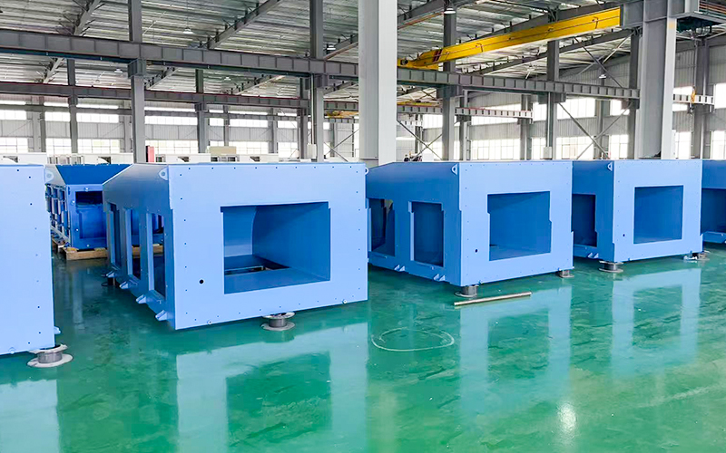
The structural differences between a heavy-duty industrial fan and its commercial variant are obvious on the plant floor. Commercial fans often utilize spot-welded, thin-gauge galvanized steel designed for clean, climate-controlled air. Industrial variants utilize thicker gauge steel plate, continuously welded housings, and heavily reinforced scroll designs. Continuous welding prevents toxic or explosive gases from leaking out of the housing during high-pressure operation. Engineers also incorporate specialized shaft seals, such as Teflon lip seals or purged mechanical seals, to completely isolate the process gas from the external environment. Specifying appropriate construction materials ensures longevity. Engineers frequently specify 316 stainless steel, fiberglass reinforced plastic (FRP), or specialized epoxy coatings. These materials resist continuous exposure to corrosives, abrasives, or high-tech manufacturing exhaust. The mass of these heavy materials also dampens operational vibration. This dampening effect further extends the lifespan of the drive components.
Aerodynamic efficiency and motor protection drive non-stop operations. A backward inclined industrial fan utilizes blades that tilt away from the direction of wheel rotation. This specific geometry offers exceptional aerodynamic efficiency. It converts a higher percentage of motor horsepower directly into airflow and pressure. Engineers specify different blade sub-types based on the exact airstream conditions. Flat backward-inclined blades offer a solid balance of efficiency and structural ruggedness. Backward-curved blades utilize a single-thickness curved profile to squeeze out slightly higher efficiency. Airfoil blades, shaped like airplane wings, offer the absolute highest efficiency and quietest operation. However, their hollow structure makes them vulnerable to erosion if abrasive dust is present.
The main advantage of the backward-inclined geometry is its non-overloading horsepower curve. In this design, the maximum brake horsepower required by the wheel occurs near its peak operating efficiency. If ductwork is suddenly removed, or a filter tears, system resistance drops to zero. A standard fan would try to move infinite air, instantly overloading and burning out the motor. A backward-inclined wheel naturally limits its own power consumption. The motor will not overload even if the system operates wide open. This makes it the safest choice for unattended, continuous duty. The primary trade-off is material handling. While highly efficient for clean air, the backward-leaning blades are susceptible to material buildup if used in heavy particulate streams.
When the airstream contains heavy dust, wood chips, or metallic shavings, efficiency takes a back seat to reliability. Radial blades extend straight out from the center hub. This paddle-wheel design is aerodynamically inefficient but excels in continuous material handling. The straight blades prevent material from accumulating, giving them self-cleaning properties. Their ruggedness allows them to withstand continuous impacts from heavy particulates that would destroy an airfoil wheel in hours. Forward-curved blades feature many small blades curved toward the direction of rotation. They move high volumes of air at lower operating speeds. However, they possess an overloading power curve and lower structural integrity. This limits their use for true high-pressure, continuous industrial duty.
Blade Geometry Comparison for Continuous Duty
| Blade Type | Aerodynamic Efficiency | Particulate Handling | Overload Risk | Best Application |
|---|---|---|---|---|
| Backward Inclined / Airfoil | Very High | Poor (Clean Air Only) | Non-Overloading | Cleanroom exhaust, general HVAC, forced draft |
| Radial | Low to Moderate | Excellent (Self-Cleaning) | Overloading | Pneumatic conveying, heavy dust exhaust |
| Forward Curved | Moderate | Poor | Overloading | Low-pressure, high-volume clean air transfer |
The physical orientation of the fan dictates how it integrates into the facility's ductwork. A single inlet industrial fan, formally known as a Single Width Single Inlet (SWSI) configuration, draws air in from one side of the housing and discharges it radially. This configuration is ideal for direct ducting on the inlet side. If a process requires pulling toxic fumes directly from a specific chemical bath, the ductwork connects straight to the single inlet flange. This ensures a sealed, leak-free pull. Field installations often utilize heavy-duty flexible connectors at these flanges to isolate fan vibration from the rigid ductwork. SWSI units are also preferred when space requirements are limited along the axis of the motor shaft. Drive arrangements typically paired with single inlet designs include direct drive and belt drive. Direct drive mounts the wheel directly on the motor shaft. Belt drive uses pulleys and belts to connect the motor to the fan shaft. Direct drive eliminates belt maintenance, making it highly desirable for continuous operation. However, it limits the ability to adjust fan speed without a variable frequency drive (VFD).
A Double Width Double Inlet (DWDI) fan essentially operates as two SWSI fans placed back-to-back within a single housing. They share a common shaft and motor. Drawing air from both sides allows the DWDI fan to handle massive air volumes at a much lower rotational speed compared to a single inlet unit of similar diameter. Lower rotational speed directly translates to extended bearing life and reduced vibration. This is highly beneficial for continuous duty. However, DWDI fans present specific footprint trade-offs. Because air must enter from both sides, they cannot be directly ducted on the inlet side easily. They require installation inside a large, pressurized plenum room. This makes DWDI fans common in massive continuous HVAC or make-up air systems where the entire mechanical room acts as the air intake. Additionally, DWDI designs often require the bearings to be mounted within the fan inlet itself, which means they are exposed to the airstream. If the air is hot or contaminated, this bearing placement requires specialized cooling tubes or protective fairings.
Matching the fan performance curve to the system resistance curve ensures continuous reliability. Every duct system has a specific resistance curve based on its length, elbows, transitions, and filters. The fan must generate the exact amount of pressure required to push the desired volume of air through that specific resistance. Operating too far left on the fan curve pushes the fan into aerodynamic stall. This causes violent vibrations that will shatter bearings. Operating too far right can cause motor overload in certain blade designs and drastically reduces efficiency. Engineers must account for the system effect. This occurs when poor duct design near the fan inlet or outlet prevents the air from entering or exiting uniformly. It effectively destroys the fan's cataloged performance ratings.
The airstream characteristics dictate the physical construction of the equipment. Evaluation dimensions include temperature extremes, moisture content, explosive gases, and particulate density. High-temperature applications require heat slingers on the shaft to dissipate heat before it reaches the bearings. They also require high-temperature grease. If the airstream contains explosive gases or dust, the fan must feature AMCA spark-resistant construction. This involves using non-ferrous materials, such as an aluminum wheel and a brass rubbing ring around the shaft opening. If a mechanical failure occurs, no sparks are generated. High-tech manufacturing environments impose stringent environmental requirements. Continuous exhaust reliability ties directly to facility safety and product yield. A single spark or a drop in exhaust pressure in a semiconductor facility can ruin product batches and endanger personnel.
In any continuous duty rotating equipment, bearings are the primary failure point. They bear the entire weight of the impeller assembly while handling the dynamic loads of high-speed rotation. Specifying the correct minimum L10 bearing life is mandatory for 24/7 operations. The L10 life rating represents the number of hours that 90 percent of a group of identical bearings will operate before showing the first signs of metal fatigue. For commercial applications, an L10 life of 40,000 hours might be acceptable. For heavy industrial continuous duty, engineers must specify an L10 life of 80,000 to 100,000 hours or more. Achieving this requires utilizing heavy-duty pillow block bearings. These are often spherical roller types, mounted on rigid steel pedestals separated from the airstream. For extremely high-speed or high-temperature applications, engineers upgrade from standard grease lubrication to circulating oil systems. Oil systems continuously flush contaminants and heat away from the rolling elements, drastically extending operational life.
At rotational speeds exceeding 1,800 RPM, even minor imperfections create destructive forces. Minor particulate buildup on the impeller blades, or uneven wear from abrasive dust, causes immediate impeller imbalance. This imbalance generates severe vibration that transfers directly through the shaft into the bearings, leading to catastrophic failure. Field engineers differentiate between static unbalance, where the heavy spot is in a single plane, and dynamic unbalance, which causes the shaft to wobble end-to-end. Mitigating this risk requires implementing continuous vibration monitoring sensors directly on the bearing housings. These sensors tie into the facility's control system, triggering alarms if vibration velocity exceeds baseline thresholds. Furthermore, the fan wheel must be dynamically balanced at the factory to strict tolerances. Adhering to the ISO 1940 standard ensures perfectly smooth operation upon installation.
Running equipment continuously requires shifting from reactive maintenance to predictive maintenance. Halting production for manual greasing is often unacceptable. Facilities must implement auto-lubrication systems that deliver precise amounts of fresh grease to the bearings at continuous intervals. This prevents both under-lubrication and over-lubrication. Thermal monitoring involves installing RTD sensors on the bearings to track temperature spikes. These spikes indicate failing lubrication or impending mechanical failure. Scheduled visual inspections of the impeller and housing should be conducted using strobe lights and inspection ports. This allows technicians to check for material buildup or blade wear without halting the rotation of the fan.
To establish a reliable predictive maintenance program, follow these field-tested steps:
Install tri-axial vibration sensors on both the inboard and outboard bearing housings to capture real-time velocity data.
Mount RTD temperature probes directly into the bearing pillow blocks and wire them to the central SCADA system.
Calibrate automatic grease lubricators based on the exact shaft speed, bearing size, and ambient operating temperature.
Establish baseline vibration signatures during the initial commissioning phase while the fan is running under full load.
Schedule monthly strobe-light inspections through the housing viewports to check for uneven particulate accumulation on the impeller blades.
Calculate your exact system static pressure and map the system resistance curve before selecting any fan model.
Specify a backward-inclined impeller geometry if your process involves clean air and requires non-overloading motor protection.
Consult with an air systems engineer to verify that your selected L10 bearing life rating aligns with your facility's continuous operational targets.
Install continuous vibration and thermal monitoring sensors on all bearing housings during the initial equipment installation phase.
A: These units utilize heavy-gauge continuously welded steel construction, high L10 bearing life ratings, and built-in structural safety margins. Their performance curves are highly stable, allowing them to resist aerodynamic stalling and surging under constant, heavy static loads.
A: This blade geometry features a non-overloading horsepower curve. The maximum power required by the wheel is reached near its peak aerodynamic efficiency. If system resistance suddenly drops and airflow increases, the power requirement decreases, preventing the motor from burning out.
A: High-pressure industrial fans feature structural reinforcements, narrower impeller widths, and higher operating speeds. They are specifically designed to push air through extreme static resistance, such as deep chemical scrubbers, whereas standard blowers handle lower pressure applications.
A: Single inlet fans are necessary when the inlet must be directly connected to ductwork, such as pulling exhaust directly from a specific machine. Double inlet fans draw air from both sides and are typically installed in open plenums to move higher volumes of air.
A: While designed for 24/7 use, maintenance should be continuous rather than periodic. Predictive maintenance tools like vibration monitoring and auto-lubrication run constantly. Major physical inspections and bearing replacements are dictated by the specific L10 bearing life rating and operational conditions.
A: The primary culprits are impeller imbalance caused by particulate buildup, improper bearing lubrication, and operating outside the fan's designed performance curve. Operating outside the curve causes aerodynamic surge and destructive vibration.


