
Views: 0 Author: Site Editor Publish Time: 2026-08-25 Origin: Site


Moving massive volumes of air efficiently presents a specific engineering challenge. You need to handle high airflow without fighting against high static pressure. Large-scale cooling, general ventilation, and industrial air circulation demand purpose-built equipment. Specifying the wrong hardware for low-resistance applications leads to immediate operational failures. We often see designers deploy centrifugal blowers for low-pressure tasks, resulting in wasted energy and oversized footprints. Conversely, pushing standard propeller designs beyond their static pressure limits causes aerodynamic stall, acoustic violations, and premature motor failure. Evaluating and specifying the correct airflow architecture prevents these drains on your facility. You must match performance curves, spatial constraints, and industry standards to your specific industrial ventilation requirements. By understanding the physics of airflow parallel to the rotating shaft, you can select equipment that maximizes Cubic Feet per Minute (CFM) while minimizing brake horsepower. This guide provides the framework for selecting the right technology to engineer high-volume, low-resistance airflow systems.
Optimal Application: Axial fans are purpose-built for high-volume, low-resistance (HVLR) environments; they excel at moving large Cubic Feet per Minute (CFM) for ventilation and cooling at static pressures typically below 1 to 2 inches of water gauge (in. w.g.).
Design Variations: Selection depends heavily on the installation environment, with options ranging from simple panel fans to high-efficiency vaneaxial designs.
The Hybrid Alternative: When system resistance slightly exceeds the capability of a standard axial fan, a mixed flow fan provides a critical middle ground without the footprint of a centrifugal blower.
Risk Mitigation: Proper inlet/outlet clearance, adherence to certified performance standards, and accurate calculation of system resistance are mandatory to prevent aerodynamic stall and turbulence.
Air movement parallel to the rotating shaft defines the core mechanics of this technology. The aerodynamic design of the aerofoil blades generates lift, similar to an airplane wing, to push air in a straight path. As the impeller rotates, the pressure difference created across the blade surface forces the air forward. This straight-through flow path maximizes airflow efficiency by eliminating the need to redirect the air 90 degrees. The direct transfer of kinetic energy from the motor to the airstream allows these units to move massive volumes of air with minimal mechanical loss. In field applications, this means you can achieve rapid air turnover in large spaces without requiring massive electrical loads.
The angle of attack on the blades determines how aggressively the air is moved. Steeper blade pitches move more air per revolution but require more motor torque and generate higher noise levels. Flatter pitches move less air but operate more quietly and consume less power. Balancing this angle against the required CFM is a primary task during the specification phase. When you look at the impeller, you will notice the blades are often twisted. The tip of the blade travels much faster than the root near the hub. The twist ensures a uniform velocity profile across the entire face of the fan, preventing localized turbulence that would otherwise degrade performance.
Understanding the performance curve dictates proper specification. The standard curve demonstrates an inverse relationship between airflow volume (CFM) and static pressure (in. w.g.). As system resistance increases, the volume of air delivered decreases. A distinct feature of this curve is the stall region. This unstable operating zone occurs when the pressure requirement exceeds the aerodynamic capability of the blades, causing airflow to separate from the surface. Operating within this dip causes severe turbulence, vibration, and a sharp drop in efficiency.
You must select an operating point on the right side of the curve, well below the stall region, to ensure stable performance. If you plot your system resistance curve over the fan performance curve, the intersection point represents your actual operating condition. If this intersection falls to the left of the peak pressure point, you are in the danger zone. Field technicians often identify a stalled unit by a distinct pulsing sound and visible shaking of the housing. Correcting this requires either reducing the system resistance by opening dampers or replacing the unit with one designed for higher static pressure.
Specific environmental parameters dictate the success of this technology. Ideal applications feature short duct runs or completely unducted configurations. The absence of dense HEPA filters, complex damper systems, or heavy cooling coils keeps static pressure low. Open-plan industrial spaces, agricultural facilities, cooling towers, and large heat exchangers represent perfect use cases. In these settings, the primary goal is rapid air exchange or bulk heat removal rather than overcoming significant duct friction.
When system resistance remains below 1.5 in. w.g., the straight-through airflow design delivers unmatched efficiency. For example, a warehouse requiring summer heat extraction relies on high ACH rates. Pushing that air through a simple wall louver creates very little resistance. An axial fan handles this effortlessly, moving tens of thousands of CFM using a fraction of the horsepower a centrifugal blower would require. You maximize your cooling capacity while keeping electrical infrastructure requirements to a minimum.
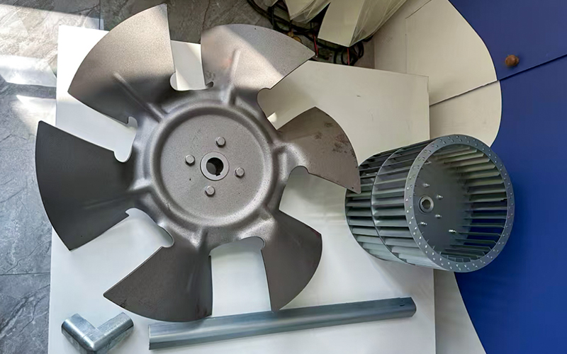
Basic panel fans consist of a propeller mounted in a flat plate or ring. They mount directly into walls or windows without ducting, serving purely for general air circulation and exhaust. They handle virtually zero static pressure. The mounting plate provides a simple way to attach the unit to a building structure, but it offers no aerodynamic guidance for the air entering or leaving the blades. Because of this, panel fans are strictly for free-air applications.
Tubeaxial fans enclose the propeller within a cylindrical housing. This housing reduces air leakage at the blade tips and allows for integration into simple, low-pressure duct systems. The tight clearance between the blade tips and the inner wall of the cylinder prevents air from slipping backward, which slightly increases the static pressure capability. While tubeaxial designs handle more resistance than panel fans, they still discharge air with a significant rotational swirl. This swirling air creates friction against the duct walls, limiting their use to relatively short, straight duct runs.
Vaneaxial designs represent a step up in aerodynamic efficiency. These units incorporate stationary guide vanes located either upstream or downstream of the impeller. The guide vanes recover rotational energy from the swirling air discharged by the blades and straighten the airflow. This straightening effect converts kinetic energy into static pressure, allowing vaneaxial models to push air through moderately longer duct systems than tubeaxial units.
The tight clearance between the blade tips and the housing further enhances efficiency. Vaneaxial units often feature precision-cast aluminum impellers and heavy-duty steel housings. They serve well in commercial HVAC applications, parking garage exhaust systems, and industrial processes requiring straight-line airflow against moderate resistance. The addition of the stator vanes makes them more expensive than tubeaxial models, but the energy savings from the increased efficiency often offsets the initial capital cost over the life of the equipment.
Facilities frequently rely on a wall mounted axial fan for versatile exhaust, supply, or destratification tasks. These units excel in warehouse cross-ventilation, pushing hot, stagnant air out of agricultural facilities, or providing direct equipment cooling. Mounting these units requires robust structural support to handle operational vibration and wind loads. Heavy-gauge steel mounting panels and vibration isolators ensure long-term stability.
Their placement high on exterior walls maximizes the intake of cooler ambient air or the rapid expulsion of indoor heat, driving effective air changes per hour without ductwork. When installing these units, you must account for prevailing winds. A strong wind blowing directly against the exhaust louver acts as additional static pressure. If the wind pressure exceeds the fan's capabilities, the airflow will stall. Installing weather hoods or specifying units with slightly higher motor horsepower mitigates this environmental variable.
When system resistance slightly exceeds standard capabilities, the mixed flow fan serves as a hybrid solution. It combines the straight-through axial flow path with centrifugal blade geometry. The air enters parallel to the shaft but discharges at a diagonal angle due to the conical hub and specialized blade shape. This design generates higher static pressure than a tubeaxial unit while maintaining a compact, inline installation footprint.
It bridges the gap between high-volume low-pressure requirements and the need to overcome moderate duct friction. You eliminate the need to upgrade to a bulky centrifugal blower. These units are particularly useful in commercial buildings where ceiling space is limited, but the ductwork includes several elbows or sound attenuators. The diagonal discharge path smoothly transitions the air back into the inline duct, minimizing turbulence and maintaining a highly efficient velocity profile.
Accurate calculation of required air changes per hour forms the baseline for sizing. You multiply the room volume by the desired ACH and divide by 60 to determine the necessary CFM. This volume requirement must then map against the total system resistance. System resistance includes the friction from every duct length, elbow, louver, and guard in the airstream. Plotting the required CFM against the calculated static pressure on the manufacturer's performance curve ensures the unit operates in its peak efficiency zone.
Field measurements often reveal discrepancies between design calculations and actual installation conditions. Using a pitot tube and an inclined manometer, technicians can measure the actual velocity pressure and static pressure in the ductwork. If the measured static pressure is higher than anticipated, the fan will deliver less CFM. This highlights the importance of conservative duct design and selecting a fan with a performance curve that allows for a slight margin of error in the static pressure calculations.
Specifying an industrial axial flow fan requires strict adherence to recognized testing standards. AMCA (Air Movement and Control Association) and ASHRAE certifications guarantee that the unit actually meets its published aerodynamic and acoustic data. Uncertified equipment often underperforms in the field, leading to inadequate cooling and unexpected noise issues. AMCA 210 governs laboratory methods for testing aerodynamic performance, while AMCA 300 covers sound testing.
Demanding certified ratings protects the system design and ensures the installed equipment delivers the specified CFM at the calculated static pressure. When reviewing submittals, always look for the AMCA seal. The testing procedures require the manufacturer to test the fan in specific configurations, such as free inlet/free outlet or ducted inlet/ducted outlet. You must ensure the tested configuration matches your planned field installation; otherwise, the published data will not accurately reflect real-world performance.
High-speed air movement inherently generates noise, primarily driven by the blade pass frequency. In commercial spaces, hospitals, or sensitive industrial environments, strict decibel (dBA) limits dictate equipment selection. A low noise mixed flow fan addresses these acoustic challenges directly. These units utilize heavy acoustic insulation within the housing and feature optimized blade pitch to minimize turbulence.
The hybrid blade geometry reduces the harsh tonal noise typically associated with standard propellers, allowing facilities to achieve high airflow volumes while maintaining compliance with indoor environmental noise standards. Sound power levels are measured across eight octave bands. When evaluating acoustic data, pay close attention to the lower frequency bands (63 Hz and 125 Hz). Low-frequency noise is notoriously difficult to attenuate with standard duct lining. Selecting a fan designed specifically for low noise generation at the source is far more effective than trying to muffle a loud fan with expensive downstream silencers.
Drive configuration dictates maintenance schedules and application suitability. Direct drive units mount the impeller directly to the motor shaft. This eliminates belts and pulleys, resulting in a compact footprint, lower maintenance requirements, and zero transmission power loss. However, the motor sits directly in the airstream. If you are exhausting hot, corrosive, or grease-laden air, a direct drive motor will fail rapidly unless it is specifically enclosed and cooled.
Belt drive configurations place the motor outside the housing, connecting to the impeller shaft via belts. This protects the motor from contaminated airstreams. Belt drives also allow for precise speed adjustments by changing pulley sizes, offering flexibility if system resistance changes after installation. The trade-off includes regular maintenance to check belt tension and replace worn belts. Belt slippage also introduces a slight power transmission loss, typically around 3 to 5 percent, which you must account for in your motor horsepower calculations.
Impeller material impacts durability and performance. Cast aluminum blades offer high strength-to-weight ratios and resist corrosion, making them ideal for heavy industrial use. Composite or glass-reinforced polyamide blades provide excellent chemical resistance and lower mass, reducing bearing wear. Steel blades are common in high-temperature applications but require protective coatings to prevent rust in humid environments.
Many high-performance units feature adjustable pitch blades. This allows technicians to manually alter the blade angle during commissioning. Adjusting the pitch tunes the performance to match actual field conditions, compensating for minor miscalculations in static pressure or changes in air density due to altitude or temperature. To adjust the pitch, technicians loosen the hub bolts, rotate each blade to the desired angle using a specialized protractor, and re-torque the bolts to the manufacturer's specifications. This flexibility prevents the need to replace the entire fan if the system requirements change slightly.
Spatial constraints heavily influence equipment selection. The straight-through airflow path offers a distinct spatial advantage. It integrates seamlessly into existing straight ductwork, acting as a continuation of the pipe. This inline installation saves significant floor and ceiling space. You can suspend these units directly from the roof structure or mount them vertically in tight mechanical shafts.
In contrast, centrifugal fans require the air to make a 90-degree turn, necessitating a scroll housing that protrudes outward. This bulky footprint complicates installation in tight mechanical rooms or crowded ceiling plenums. When retrofitting an older building with limited mechanical space, the inline alternative often proves to be the only viable option for straightforward ventilation runs without requiring major structural modifications.
For bulk air movement at low static pressures, inline propeller designs require significantly lower brake horsepower (BHP) than centrifugal blowers. The direct transfer of kinetic energy without redirecting the airflow minimizes mechanical and aerodynamic losses. This higher efficiency translates directly to lower electrical consumption. Over a 10-to-15-year lifecycle, the reduced energy draw yields substantial operational cost savings.
Centrifugal units operating in low-resistance environments often run inefficiently. They draw excess amperage and drive up utility bills without providing proportional airflow benefits. If you place a centrifugal fan in a free-air exhaust application, it will try to move so much air that it overloads the motor. You would have to artificially restrict the airflow with a damper just to keep the motor from tripping the breaker, which defeats the purpose of the installation.
Despite their efficiency in open environments, inline propeller designs fail when confronted with high system resistance. They lack the centrifugal force required to push air through complex, multi-branch ducting, heavy HEPA filtration systems, or dense cooling coils. When forced against high static pressure, the air slips back over the blades, causing the unit to stall.
In these high-resistance scenarios, you must shift to centrifugal blowers. Centrifugal designs utilize centrifugal force to generate the high static pressure necessary to overcome severe duct friction and dense system components. Attempting to use a standard propeller fan to push air through a MERV 14 filter bank will result in zero airflow and a burned-out motor within hours.
Performance Comparison Chart
| Feature | Axial Design | Centrifugal Design |
|---|---|---|
| Airflow Path | Straight-through (Parallel to shaft) | 90-degree turn (Perpendicular to shaft) |
| Static Pressure Capability | Low to Moderate (Typically < 2 in. w.g.) | High to Very High (Up to 10+ in. w.g.) |
| Volume (CFM) | Very High | Moderate to High |
| Installation Footprint | Compact, Inline | Bulky, requires scroll housing |
| Energy Efficiency (Low Pressure) | Excellent | Poor |
The "System Effect" represents the most common cause of underperformance in the field. This phenomenon occurs when duct configurations disrupt the uniform velocity profile entering or exiting the unit. Placing elbows, dampers, or abrupt transitions too close to the inlet starves the impeller of air, causing uneven loading on the blades. This uneven loading not only reduces CFM but also causes severe vibration that destroys bearings.
Similarly, restricting the discharge prevents the air from recovering static pressure. You must ensure straight duct runs of at least three to five duct diameters on both the inlet and outlet to guarantee the unit delivers its rated CFM. If spatial constraints make this impossible, you must apply a system effect derating factor to your calculations and select a larger fan to compensate for the inevitable loss in performance.
Operating in the stall region damages equipment rapidly. Physical symptoms of aerodynamic stall include severe vibration, a low-frequency surging or pulsing noise, and fluctuating motor amperage. These conditions occur when the actual system resistance is higher than calculated, forcing the operating point into the dip on the performance curve.
Mitigation requires accurate upfront static pressure calculations. If a system exhibits surge post-installation, technicians must either decrease system resistance or adjust the blade pitch if the motor has sufficient horsepower capacity. Decreasing resistance might involve cleaning dirty coils, opening balancing dampers, or removing unnecessary duct fittings. Ignoring a surging fan guarantees catastrophic mechanical failure, usually starting with shattered bearings or cracked impeller blades.
Common Stall Symptoms and Field Diagnostics
| Symptom | Probable Cause | Field Action Required |
|---|---|---|
| Low-frequency pulsing noise | Airflow separation from blades (Stall) | Measure static pressure; open dampers to reduce resistance. |
| Fluctuating motor amperage | Unstable operating point on curve | Check for blocked filters or closed fire dampers. |
| Severe housing vibration | Uneven blade loading due to System Effect | Inspect inlet clearance; remove obstructions within 3 duct diameters. |
| Zero airflow despite motor running | Complete aerodynamic stall | Shut down immediately; recalculate system static pressure requirements. |
Safety and maintenance access dictate the physical installation parameters. OSHA compliance mandates robust safety guards on any unit accessible to personnel, particularly wall-mounted exhausters located near floor level. These guards must prevent fingers or tools from contacting the rotating impeller. The mesh size of the guard must comply with specific safety standards based on the distance from the moving parts.
Vibration isolation mounts—either spring or neoprene—are necessary to prevent the transmission of harmonic frequencies into the building structure. Finally, you must specify access doors in the adjacent ductwork or housing to allow maintenance personnel to inspect belts, lubricate bearings, and clean the blades without dismantling the entire duct system. Dirt buildup on the blades alters the aerofoil shape, reducing efficiency and causing imbalance. Regular cleaning schedules prevent this degradation.
Inspect belt tension and alignment every 30 days on belt-driven units.
Lubricate fan shaft bearings according to the manufacturer's specified intervals, avoiding over-greasing which blows out the seals.
Clean impeller blades quarterly to maintain aerodynamic efficiency and prevent imbalance.
Check all mounting bolts and vibration isolators for tightness during routine inspections.
Calculate your exact system static pressure using field measurements to ensure the operating point falls safely below the aerodynamic stall region.
Consult manufacturer performance curves and demand AMCA-certified data to verify aerodynamic and acoustic ratings before finalizing your submittals.
Design your ductwork to provide at least three to five duct diameters of straight clearance at both the inlet and outlet to prevent the system effect.
Engage with an applications engineer to finalize motor specifications, drive types, and blade pitch adjustability based on your specific site conditions.
A: An axial unit moves air parallel to its rotating shaft. This provides high airflow at low static pressure in a compact, inline footprint. A centrifugal unit draws air in parallel to the shaft but discharges it at a 90-degree angle. This generates higher static pressure suitable for complex ductwork and heavy filtration.
A: Specify a wall-mounted unit for cross-ventilation, spot cooling, or when roof access is limited. They work perfectly for pushing hot air out of warehouses or agricultural buildings directly through exterior walls. This avoids the need for vertical ductwork and roof penetrations, simplifying installation and reducing structural load.
A: A mixed flow unit combines axial and centrifugal blade geometries. Air flows inline, but the conical hub and blade shape discharge air diagonally. This generates higher static pressure than a standard axial unit while maintaining a smaller footprint than a centrifugal blower. It bridges the gap for medium-resistance applications.
A: Stall occurs when system resistance exceeds the aerodynamic capability of the blades. This causes airflow separation and severe turbulence. Prevent it by accurately calculating system resistance before installation. Always select a unit where the operating point sits well below the stall curve on the manufacturer's performance chart.
A: They handle moderate static pressure better than standard tubeaxial units. However, they are not suitable for very high-static pressure systems, such as those with dense HEPA filters. They serve best in medium-resistance commercial applications that require strict acoustic compliance and inline installation.
A: Determine the volume of the space by multiplying length, width, and height. Multiply that volume by the required Air Changes per Hour (ACH) dictated by building codes or specific cooling needs. Divide that final number by 60. This gives you the required Cubic Feet per Minute (CFM).
A: The system effect is a loss of performance caused by uneven airflow entering or exiting the unit. Placing elbows, dampers, or obstructions too close to the fan disrupts the velocity profile. This drastically reduces the actual CFM delivered to the space compared to the fan's rated capacity.


